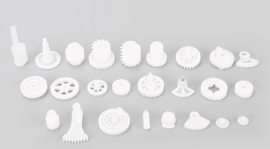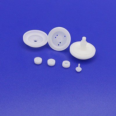
Key points
- Below module 1 mm, a finger gear is not a scaled-down normal gear: the tooth becomes smaller than errors that were negligible at larger sizes.
- The hard part is holding tooth thickness and bore position steady when a few microns decide smooth running or a jam.
- Our factory builds micro gears from module 0.1, and our micro gearboxes span Ø 3.4–38 mm with ratios of 5–1500.
- A sample gear of module 0.320 with 9 teeth measured JGMA grade 0 on a double-flank roll tester: total composite error 4.1 µm, tooth-to-tooth error 2.8 µm, runout 1.4 µm.
A humanoid robot hand asks a plastic gear for the near-impossible: fit inside a fingertip-wide finger joint, transmit enough torque to grip, and reverse thousands of times a day. Below module 1 mm, the tooth is so small that errors a normal gear can ignore — a few microns of shrinkage, an off-centre bore, a burr on one flank — become a large fraction of the tooth itself.
Why a robot finger is the hardest job for a plastic gear
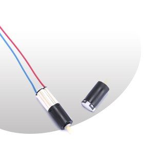
A finger joint is small in every direction. The gearbox must fit the finger's diameter, the motor sits beside it rather than behind it, and the gear train folds back on itself to reach the reduction a finger needs. Our micro gearboxes cover Ø 3.4–38 mm, ratios 5–1500, torque 1 gf·cm to 50 kgf·cm — because a finger, a wrist and an elbow each need a different corner of that range. A finger drive lives at the small-diameter, high-ratio end, where the last-stage gears are the smallest and carry the full output torque.
The duty makes it worse. A finger does not rotate continuously like a fan motor: it starts, stops, reverses, holds a grip, and sometimes stalls on something hard. Stall is the dangerous case — the motor keeps pushing, the tooth keeps bending, and heat builds up where it is thinnest.
What changes below module 1 mm
Gear module is the size of the tooth, in millimetres: module 1 means a tooth roughly 2.25 mm tall, module 0.3 a tooth about 0.7 mm tall — and every rounding error becomes a design problem.
| Module | Approx. tooth height | What it means in practice |
|---|---|---|
| 1.0 | ≈ 2.25 mm | Standard tooling and measurement |
| 0.5 | ≈ 1.1 mm | Mold detail and gate position start to matter |
| 0.3 | ≈ 0.7 mm | Shrinkage must be predicted per material and cavity |
| 0.2 and below | ≈ 0.45 mm or less | Every step — tooling, molding, measuring — needs its own process |
Halving the module roughly doubles the share of every error. A mold cavity 5 µm out of round is invisible on a module 1 gear and a real problem on a module 0.2 gear. So a supplier who quotes from the drawing alone, without asking about the duty, is a warning sign.
The five things that go wrong first
When a sub-1 mm gear fails, the cause is usually one of five.
1. The mold cannot reproduce the tooth
At module 0.2–0.3 the tooth cavity is smaller than a grain of sand, cut by wire and sinker EDM into hardened steel. A cavity with a dull edge or a rough flank copies that roughness onto every gear. Our tooling is made in-house, so mold maker, molding engineer and gear inspector work on the same part in one building — and a correction reaches the cavity the same day.
2. Shrinkage moves the tooth after molding
Every plastic shrinks as it cools, and POM, PA, PC and ABS each shrink differently. On a module 0.3 gear, a shrinkage estimate off by a fraction of a percent moves tooth thickness by several microns, enough to change backlash from correct to binding. So the mold is cut for one specific material, and shrinkage is confirmed on first samples before any production cavity is released.
3. The bore is not where the teeth think it is
A gear can have perfect teeth and still run badly if the bore is eccentric. Runout makes the mesh tight on one side of the revolution and loose on the other, so the finger feels smooth for half a turn and gritty for the other half. That is why we measure runout on the same roll tester that checks the teeth.
4. Measurement cannot see the problem
A micrometer cannot measure a module 0.2 tooth. What works is the double-flank roll test: the gear is rolled against a master gear and the centre-distance variation is recorded, catching thickness, profile, pitch and runout errors together. Our capabilities page describes a sample measurement on this method: a sample gear of module 0.320 with 9 teeth measured JGMA grade 0, with total composite error 4.1 µm, tooth-to-tooth composite error 2.8 µm and runout 1.4 µm. That is a sample report, not a promise — but it shows what the measurement chain can resolve.
5. Assembly damage nobody notices
The last risk is not in the gear at all. A micro gear pressed onto a shaft with a fraction too much interference, or nicked by tweezers on a flank, arrives already damaged. So the gear should be designed for its assembly method — a D-bore or a controlled press fit, not a force fit — and packed so teeth never touch in transit.
What to check before you order
Five questions separate a supplier who can do sub-1 mm work from one who is guessing. What is the smallest module they have molded in production — not in a trial? How do they measure tooth accuracy at that module — a supplier who cannot name the method is not measuring it. Which material would they choose and why? POM is the usual default; the trade-offs against nylon are in our POM vs nylon comparison. How is backlash held across the batch, and how are gears packed so teeth do not touch? And what happens at stall: a supplier who has thought about grip-and-hold will answer about tooth bending and heat, not just quote a catalogue torque figure. Below module 1 mm there is no margin left to absorb a supplier's optimism; the only reliable proof is a measured sample.
Frequently asked questions
What module do humanoid robot finger gears usually use?
Most finger-joint gears sit in the module 0.2–0.5 range, with the smallest pinions down to module 0.1. Our factory molds micro gears from module 0.1, so the full range is covered from one tooling and measurement setup.
Can plastic gears handle the torque in a robot finger?
Yes, within their design envelope. A finger gear train multiplies motor torque through several stages, so the final gears see high torque but low speed — the duty plastic handles well, provided the material is chosen for the stall case. Our micro gearboxes deliver up to 50 kgf·cm, which covers the grip forces of a human-scale hand.
Designing a hand, a gripper or a small actuator with gears below module 1 mm? Send us the drawing with the torque, speed and stall conditions, and we will come back with a material recommendation, a measurement plan and a quotation.